
This has to have been the easiest build of the project so far. I'm not quite sure why, but I was able to build this board from start to finish in about 3 evenings. It was certainly refreshing not having to spend weeks on it, and satisfying as the results were very rapid (rather unlike the timeliness of this post...)
The build starts as usual with the bus connectors. The time decoder board is going to be very much toward the front of the clock, in fact it'll likely interface directly with the display board, so it has all of the bus connectors on it, even if most of the pins within lay un-used by this board - it still has to carry all of the signals from the rest of the clock through to the display board.
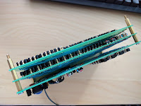
I tried something a little different this time, however. In prior builds I had added supply (9V DC) and ground "busses" across the board as I went along, but it became a bit painful constantly modding new ones in as the build progressed, so this time I laid them all out in one go.


Then I start to solder in all of the transistors and resistors that will make up the gates. If you happen to be wondering how I get large numbers of them in at a time without a load of hassle, blu tack is your friend:


I borrowed the blu tack technique from Julian Ilett, a YouTuber that I follow (although I'm sure he wasn't the first to do it either, though he's certainly the first that I've seen do it...)
Then it's a process of wiring everything together on a decoder by decoder basis, and test each one as I go along so that I can catch faults progressively and early.
Testing was achieved with a "jig" that I rigged up on a breadboard. Although I had originally planned to, and thought that I had bought common cathode displays, it turns out I bought common anode displays instead. Using common cathode I had planned to have the final "driving" gates of the decoders control the flow of current to the LED segments, but now with common anode displays I'll be sticking resistors and transistors on the display board along side the displays they will control. The transistors will connect the cathode of each segment down to ground when its decoder output is high, so it'll achieve the same result but use a few more transistors and resistors (not like I'm short of them...)


In the right hand picture above you see what is the units seconds decoder connected to the time module and then onwards to the test jig. I even managed to create an animated GIF showing it counting through all of the digits.
I worked my way through all 6 of the decoders very quickly and they all worked without a hitch so unfortunately there's no troubleshooting to speak of, but here's the end product including a bonus photo of how the stack is coming along now (and it's starting to feel kind of weighty!):


On to the next one I guess!
The build starts as usual with the bus connectors. The time decoder board is going to be very much toward the front of the clock, in fact it'll likely interface directly with the display board, so it has all of the bus connectors on it, even if most of the pins within lay un-used by this board - it still has to carry all of the signals from the rest of the clock through to the display board.
I tried something a little different this time, however. In prior builds I had added supply (9V DC) and ground "busses" across the board as I went along, but it became a bit painful constantly modding new ones in as the build progressed, so this time I laid them all out in one go.


Then I start to solder in all of the transistors and resistors that will make up the gates. If you happen to be wondering how I get large numbers of them in at a time without a load of hassle, blu tack is your friend:


I borrowed the blu tack technique from Julian Ilett, a YouTuber that I follow (although I'm sure he wasn't the first to do it either, though he's certainly the first that I've seen do it...)
Then it's a process of wiring everything together on a decoder by decoder basis, and test each one as I go along so that I can catch faults progressively and early.
Testing was achieved with a "jig" that I rigged up on a breadboard. Although I had originally planned to, and thought that I had bought common cathode displays, it turns out I bought common anode displays instead. Using common cathode I had planned to have the final "driving" gates of the decoders control the flow of current to the LED segments, but now with common anode displays I'll be sticking resistors and transistors on the display board along side the displays they will control. The transistors will connect the cathode of each segment down to ground when its decoder output is high, so it'll achieve the same result but use a few more transistors and resistors (not like I'm short of them...)


In the right hand picture above you see what is the units seconds decoder connected to the time module and then onwards to the test jig. I even managed to create an animated GIF showing it counting through all of the digits.
I worked my way through all 6 of the decoders very quickly and they all worked without a hitch so unfortunately there's no troubleshooting to speak of, but here's the end product including a bonus photo of how the stack is coming along now (and it's starting to feel kind of weighty!):


On to the next one I guess!
No comments:
Post a Comment